Flow Base
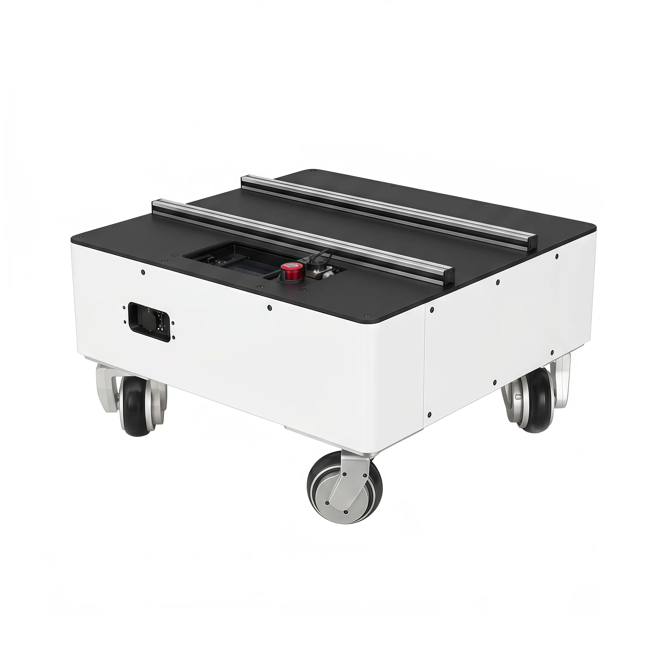
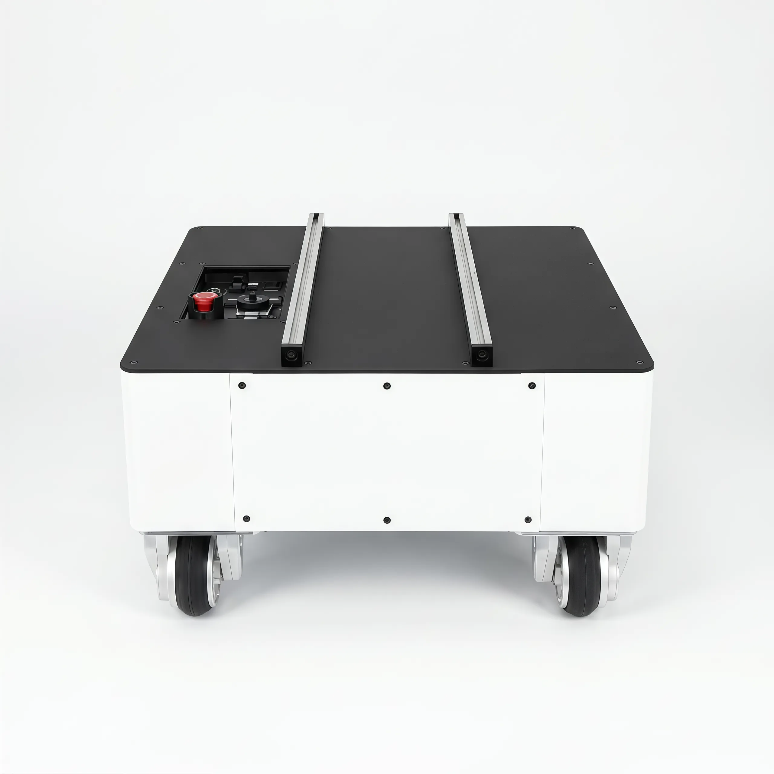
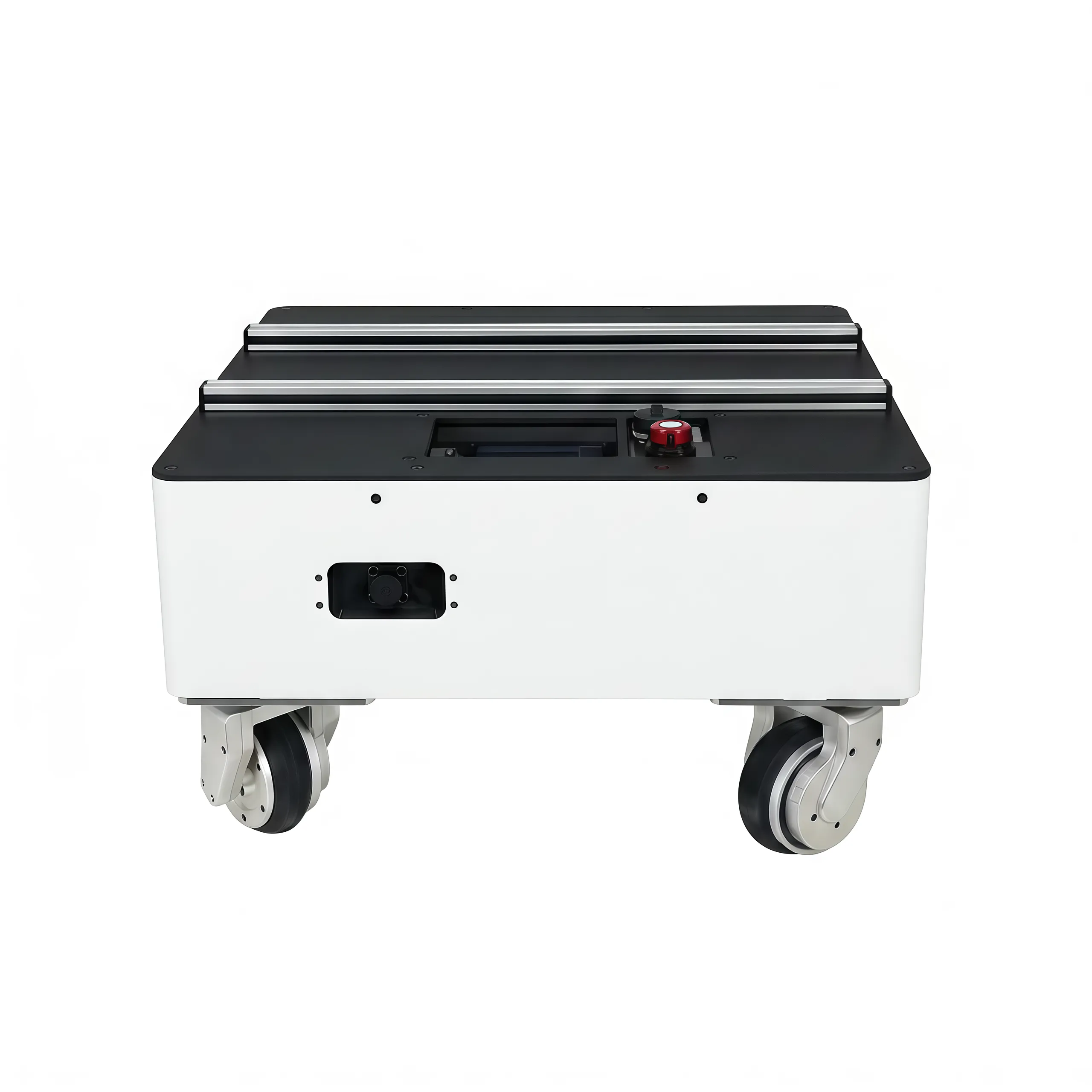
Flow Base is I2RT's omnidirectional holonomic mobile platform. Designed to pair with YAM arms, it enables precise whole-body mobile manipulation for tasks that demand exact positioning and free orientation.
Tagline
"It likes to move it move it" — precise, omnidirectional control for tasks where positioning and stability are critical.
Key Features
- Holonomic drive — simultaneous XY translation and rotation with no kinematic constraints
- On-board Raspberry Pi — pre-configured with i2rt SDK; SSH-accessible over Wi-Fi or Ethernet
- CAN bus motor control — same DM-series protocol as YAM arms
- Remote controller — joystick remote included for manual operation
- API control — full network Python API via
FlowBaseClient - Odometry — wheel odometry with reset; external sensor integration supported
- Safety — E-stop, velocity timeout (0.25 s), remote override
Specifications
| Parameter | Value |
|---|---|
| Drive | Holonomic (4-wheel) |
| Communication (external) | Ethernet (static IP 172.6.2.20) / Wi-Fi |
| Communication (motors) | CAN bus |
| On-board computer | Raspberry Pi |
| Power | Internal battery |
| SSH credentials | i2rt / root |
| API port | 11323 |
| Velocity timeout | 0.25 s |
Photos & Videos
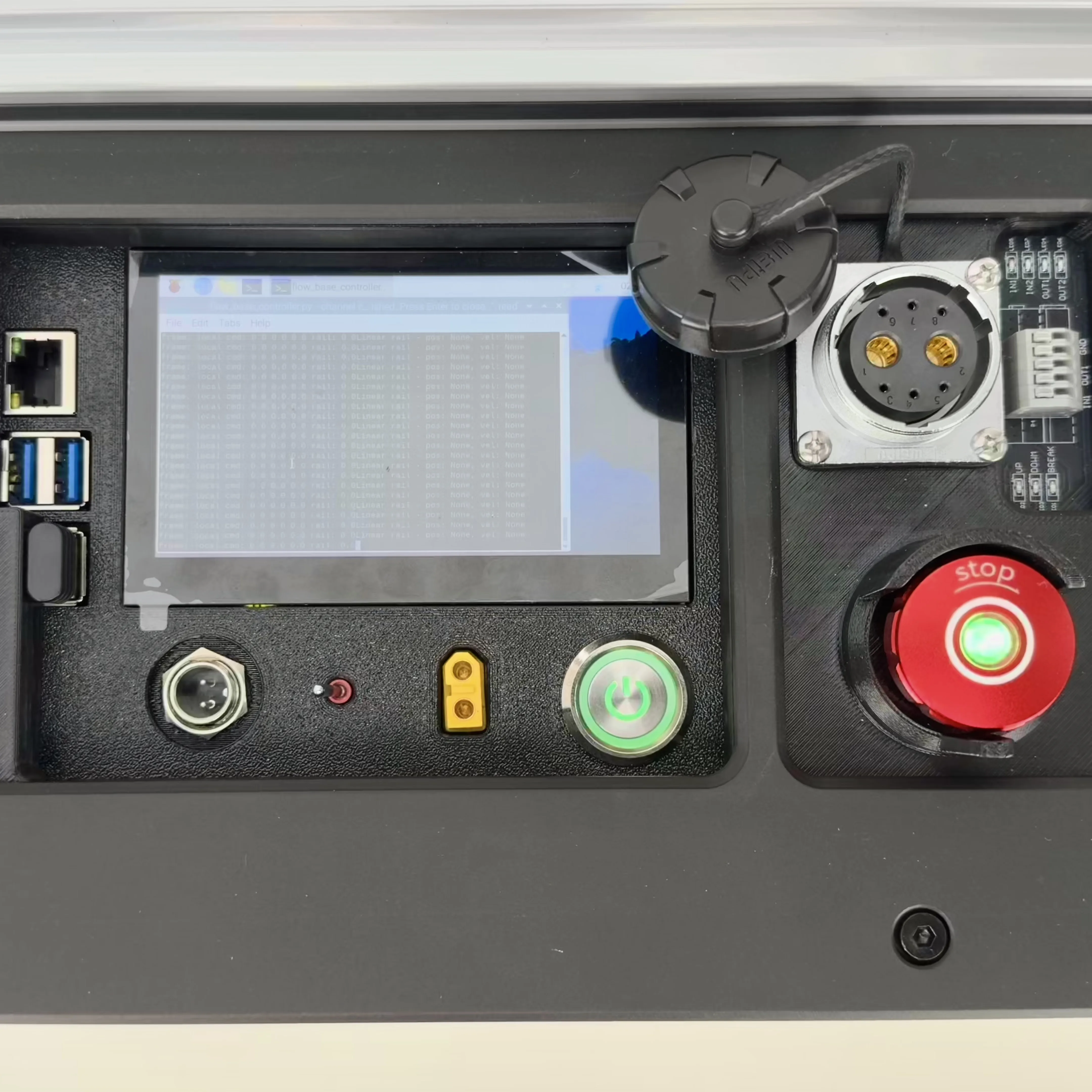
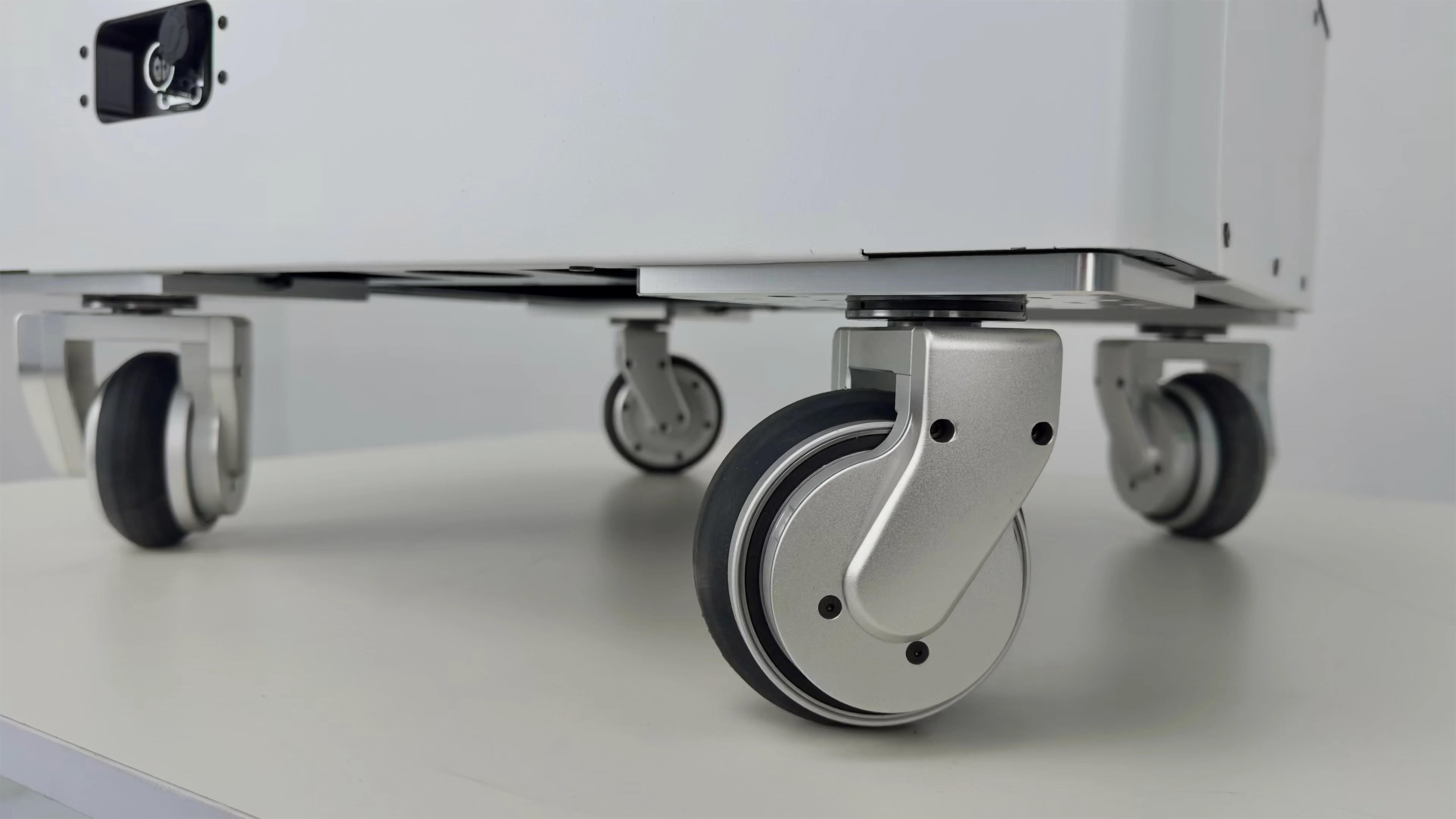
Hardware Setup
Get the Flow Base omnidirectional mobile platform unboxed, powered, and joystick-ready.
Prerequisite
SW Setup is not required — the Flow Base ships with a Raspberry Pi pre-configured with the SDK. You only need network access to SSH in.
1. Unbox
- [ ] Flow Base chassis
- [ ] Battery pack (already installed)
- [ ] Joystick remote controller
- [ ] Ethernet cable (for wired SSH)
- [ ] Charger
2. Power on
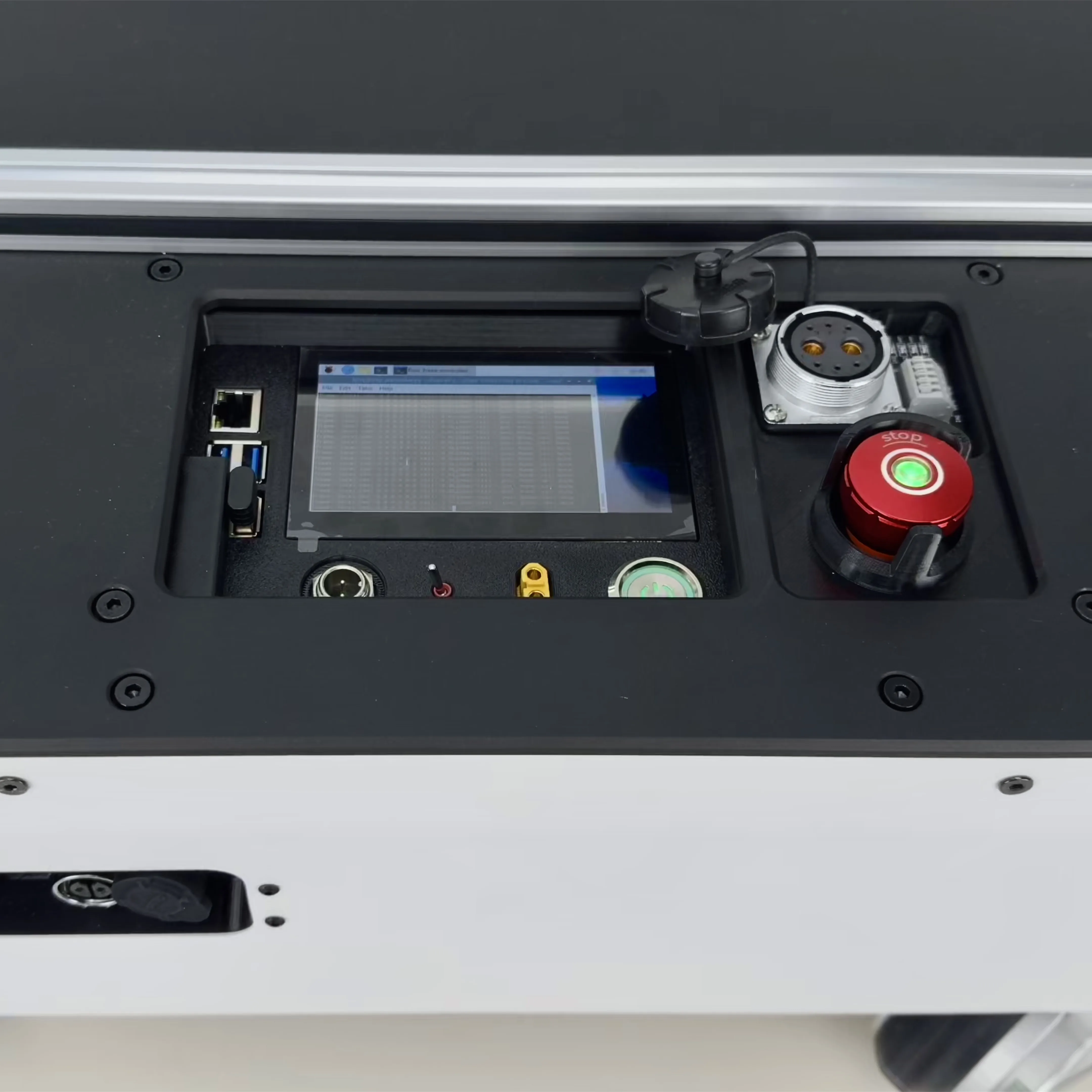
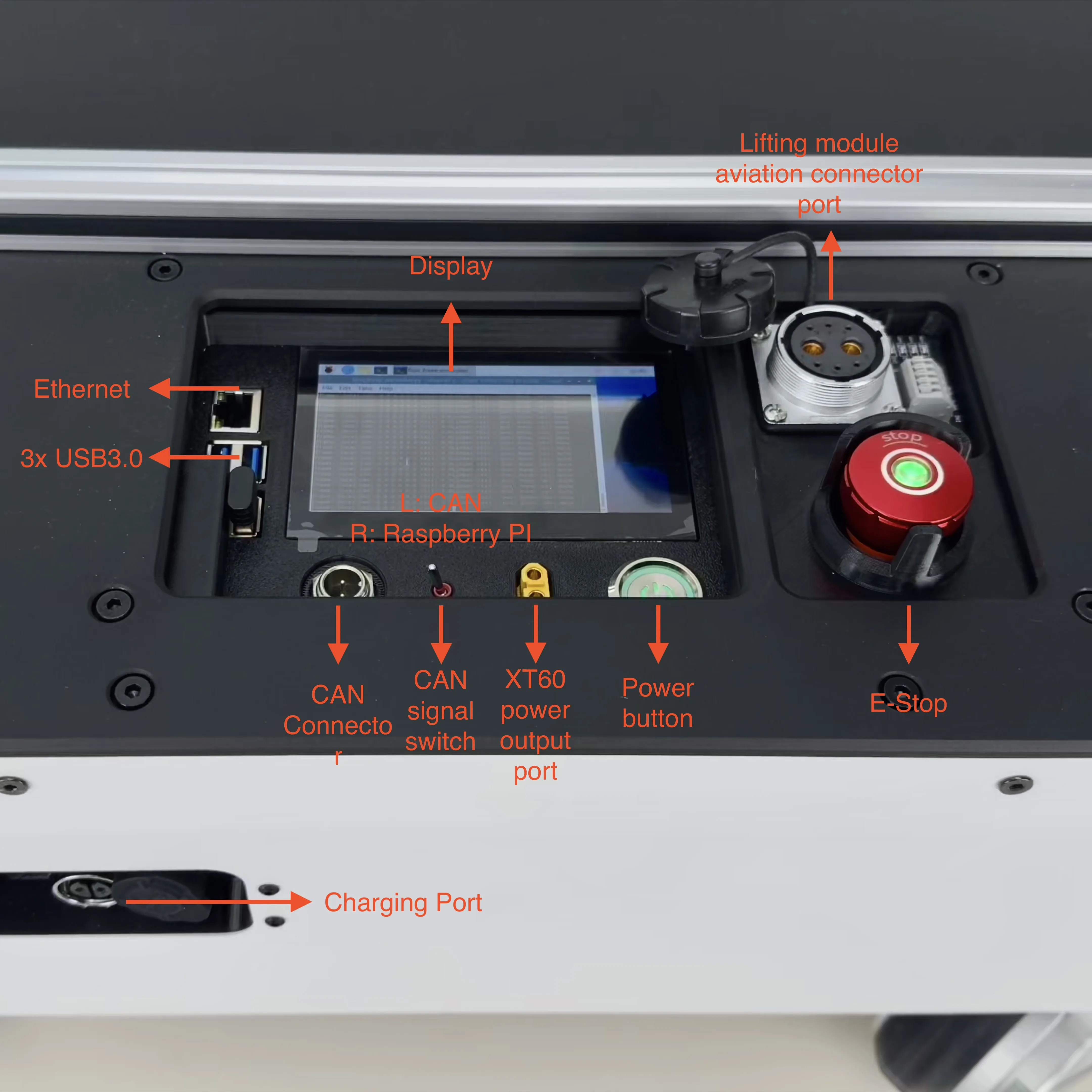
- [ ] Twist the E-stop button counter-clockwise to release it
- [ ] Set the CAN selector switch to UP position (selects the on-board Pi as CAN master)
- [ ] Press the power button — the Pi display should light up
- [ ] Wait ~30 seconds for the Pi to finish booting
3. Connect to the Pi
# Wired (recommended) — static IP
ssh i2rt@172.6.2.20
# Password: root
Wi-Fi setup
If you prefer Wi-Fi, connect a keyboard + monitor to the Pi the first time and run sudo raspi-config to join your network.
4. Verify the SDK is current
cd ~/i2rt && git pull5. Test with the joystick
On the Pi (pass --gamepad to enable joystick input):
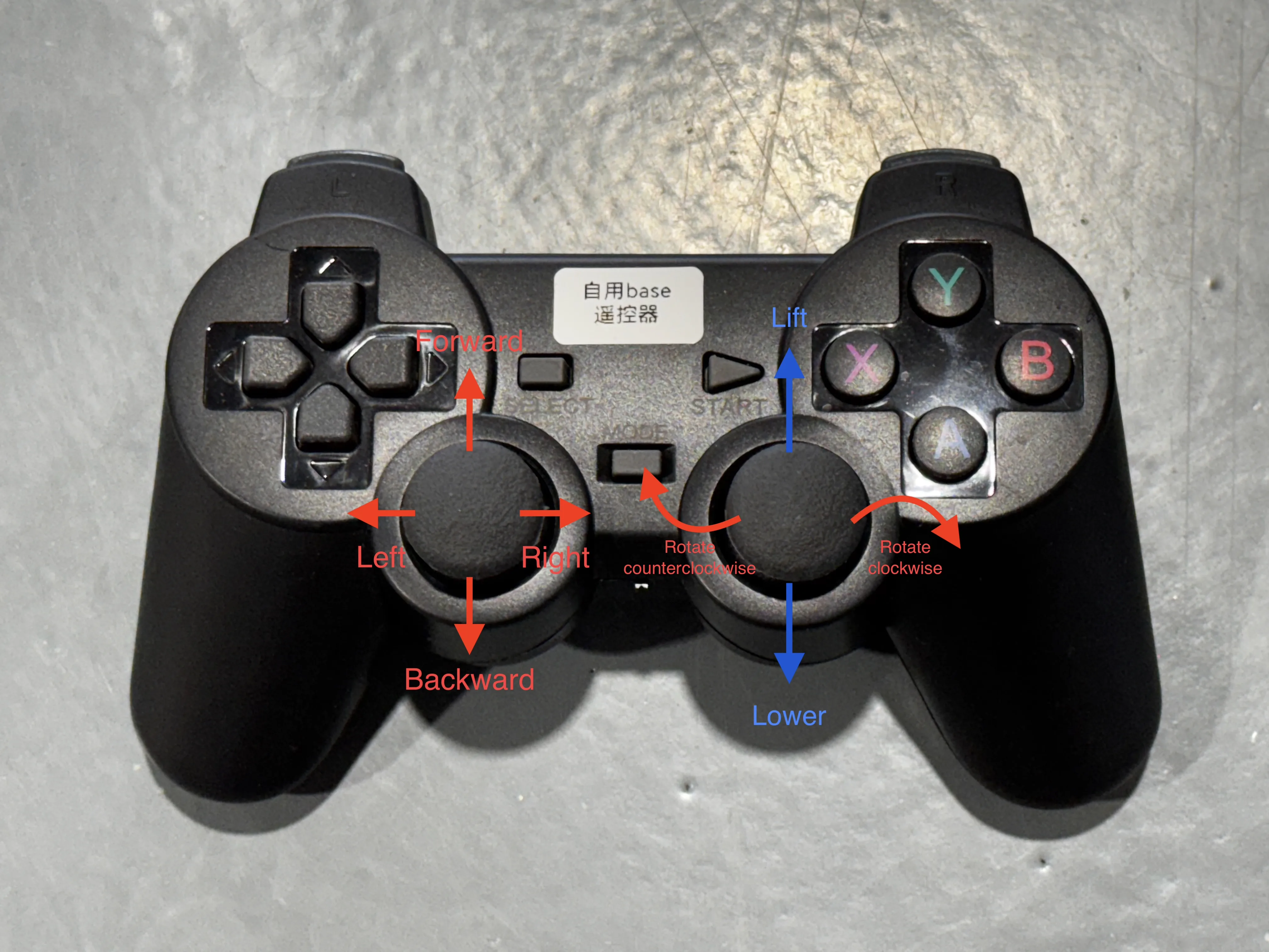
python i2rt/flow_base/flow_base_controller.py --gamepad- [ ] Left joystick → base translates (XY)
- [ ] Right joystick X → base rotates (yaw)
- [ ] Press Left2 to override API commands (safety)
Quick Start Demo
Drive the Flow Base with the joystick remote, then control it programmatically.
1. Joystick demo (on the Pi)
ssh i2rt@172.6.2.20
python i2rt/flow_base/flow_base_controller.py --gamepad
Without --gamepad the controller runs on remote/API commands only (no joystick). See the Remote Control Layout below for the full button reference.
2. Python API — drive forward from a laptop
From your laptop (on the same network):
from i2rt.flow_base.flow_base_client import FlowBaseClient
import numpy as np
import time

client = FlowBaseClient(host="172.6.2.20")

# Drive forward at 0.1 m/s for 2 seconds
start = time.time()
while time.time() - start < 2.0:
    client.set_target_velocity(np.array([0.1, 0.0, 0.0]), frame="local")
    time.sleep(0.05)

# Read odometry
print(client.get_odometry())
client.close()
Velocity timeout
The base stops automatically if no command arrives within 0.25 seconds. The client maintains a heartbeat thread (20 ms) while connected.
For the full SDK (linear rail, frame conventions, advanced commands), see the API Reference section below.
Remote Control Layout
| Input | Function |
|---|---|
| Left joystick | XY translation |
| Right joystick X | Rotation (yaw) |
| Right joystick Y | Linear rail lift (if equipped) |
| Left1 | Reset odometry |
| Mode | Toggle local ↔ global frame |
| Left2 | Override API commands (safety) |
Coordinate Systems
The base supports two control frames toggled with the Mode button on the remote:
| Mode | Behaviour |
|---|---|
| Local | XY motion is relative to the base's current heading |
| Global | XY motion is relative to the world frame (headless mode) |
Odometry drift
Wheel odometry accumulates error, especially during aggressive movements. For precise mobile manipulation, integrate a visual odometry sensor (RealSense T265, ZED Camera). Press Left1 to reset odometry at any time.
API Reference
The Flow Base SDK has two layers:
| Class | Location | Use |
|---|---|---|
Vehicle | flow_base_controller.py | Runs on-board the Pi — joystick demo |
FlowBaseClient | flow_base_client.py | Runs remotely — network Python API |
FlowBaseClient
For remote control from your development machine.
from i2rt.flow_base.flow_base_client import FlowBaseClient

client = FlowBaseClient(
    host="172.6.2.20",
    with_linear_rail=False,
)| Parameter | Type | Default | Description |
|---|---|---|---|
host | str | "localhost" | IP address of the Flow Base Pi |
with_linear_rail | bool | False | Set True if the linear rail module is installed |
No port parameter
The port is hardcoded internally using BASE_DEFAULT_PORT. You only need to specify the host IP.
Movement Commands
set_target_velocity(velocity, frame)
import numpy as np

# 3D (base only)
client.set_target_velocity(np.array([vx, vy, omega]), frame="local")

# 4D (base + linear rail)
client.set_target_velocity(np.array([vx, vy, omega, rail_vel]), frame="local")| Parameter | Unit | Description |
|---|---|---|
vx | m/s | Forward/backward |
vy | m/s | Left/right (strafe) |
omega | rad/s | Rotation (yaw rate) |
rail_vel | m/s | Linear rail speed (positive = up) |
frame | — | "local" (relative to base) or "global" (world frame) |
Velocity must be a NumPy array
set_target_velocity() expects a np.ndarray with shape (3,) or (4,). Pass np.array([...]), not a plain Python list.
Velocity timeout
The base stops automatically if no command arrives within 0.25 seconds. FlowBaseClient maintains a heartbeat automatically while connected via a background thread (20 ms interval).
Odometry
get_odometry() → dict
odom = client.get_odometry()
# {
#   'position': {'translation': array([x, y, z]), 'rotation': theta},
#   'velocity': {
#     'world': {'translation': array([vx, vy, vz]), 'rotation': omega},
#     'body':  {'translation': array([vx, vy, vz]), 'rotation': omega},
#   },
# }
# z / vz are 0.0 on a bare base; they carry the rail height / rate on a Linear Bot.
Wheel odometry only. Errors accumulate over time — integrate visual odometry (RealSense T265, ZED) for precise localization.
reset_odometry() → None
Resets position and heading to zero.
Linear Rail API
Only available when with_linear_rail=True.
get_linear_rail_state() → dict
state = client.get_linear_rail_state()
# {
#   'position': {'motor': float (rad), 'linear': float (m) | None},
#   'velocity': {'motor': float (rad/s), 'linear': float (m/s) | None},
#   'upper_limit_triggered': bool,
#   'lower_limit_triggered': bool,
#   'brake_on': bool,
#   'initialized': bool,
#   'meters_per_rad': float | None,
#   'eff': float,
# }
# 'linear' fields are None until the rail is calibrated (meters_per_rad known).
set_linear_rail_velocity(velocity: float) → None
client.set_linear_rail_velocity(0.5)    # raise
client.set_linear_rail_velocity(0.0)    # stop
client.set_linear_rail_velocity(-0.5)   # lower
Combined base + rail command
client.set_target_velocity(np.array([vx, vy, omega, rail_vel]), frame="local")Auto-homing
The rail homes to the lower limit switch on init. Ensure clearance below before powering on.
Cleanup
Always close the client when done to stop the background heartbeat thread:
client.close()Command-line Client
Quick functional tests without writing Python:
# Read odometry
python i2rt/flow_base/flow_base_client.py --command get_odometry --host 172.6.2.20

# Reset odometry
python i2rt/flow_base/flow_base_client.py --command reset_odometry --host 172.6.2.20

# Run a short movement test (base will move)
python i2rt/flow_base/flow_base_client.py --command test_command --host 172.6.2.20

# Test linear rail (rail will move)
python i2rt/flow_base/flow_base_client.py --command test_linear_rail --host 172.6.2.20

# Monitor linear rail state
python i2rt/flow_base/flow_base_client.py --command get_linear_rail_state --host 172.6.2.20
Vehicle (On-board Controller)
Runs directly on the Pi. Used for the joystick demo.
from i2rt.flow_base.flow_base_controller import Vehicle
import time

# Vehicle() auto-starts its control thread (auto_start=True by default);
# do NOT call start_control() again or the thread starts twice.
v = Vehicle()

start = time.time()
while time.time() - start < 2.0:
    v.set_target_velocity((0.15, 0.0, 0.0), frame="local")
Coordinate Frames
| Frame | Description |
|---|---|
local | Relative to the current base orientation. Joystick forward = robot forward regardless of heading. |
global | World frame from odometry zero. Similar to drone headless mode. Accumulates error. |
Switch frames at runtime via the remote Mode button, or programmatically by passing frame= to set_target_velocity.
External CAN Control
To bypass the on-board Pi and control the base from an external computer:
- Connect your CAN adapter to the external CAN connector
- Set the CAN selector switch to the DOWN position
- Clone the i2rt repo on your external machine and control via CAN directly
Troubleshooting
| Symptom | Fix |
|---|---|
| Remote unresponsive | Toggle remote off and on to wake from sleep |
| Slow boot | Normal — screen firmware adds delay, SSH is available quickly |
| Inaccurate odometry | Expected with wheel odometry; use external visual sensor for precision |
| Linear rail not homing | Check GPIO connections and limit switches |
| Linear rail stuck at limit | Run get_linear_rail_state() to check switch status |
Commissioning SOP
Standard operating procedure for commissioning the Flow Base drive system — motor ID/parameter configuration, drive-direction setup, steering zero calibration, and functional verification. Follow this end to end when bringing up a newly assembled base.
CAN interface
All CAN interfaces default to can0 — no interface renaming is required.
1. Motor ID & Parameter Configuration
1.1 Motor ID assignment
Viewed from the top of the base, IDs are assigned as follows:
| Physical position | caster_idx | Motor role | CAN ID | Motor model | Master ID |
|---|---|---|---|---|---|
| Front-left | 2 | Steering | 3 | DM4310V | 19 |
| Drive | 4 | DMH6215 / DM4310V | 20 | ||
| Front-right | 3 | Steering | 5 | DM4310V | 21 |
| Drive | 6 | DMH6215 / DM4310V | 22 | ||
| Rear-right | 4 | Steering | 7 | DM4310V | 23 |
| Drive | 8 | DMH6215 / DM4310V | 24 | ||
| Rear-left | 1 | Steering | 1 | DM4310V | 17 |
| Drive | 2 | DMH6215 / DM4310V | 18 |
Note: Master ID = CAN ID + 16 (required by the DM motor protocol).
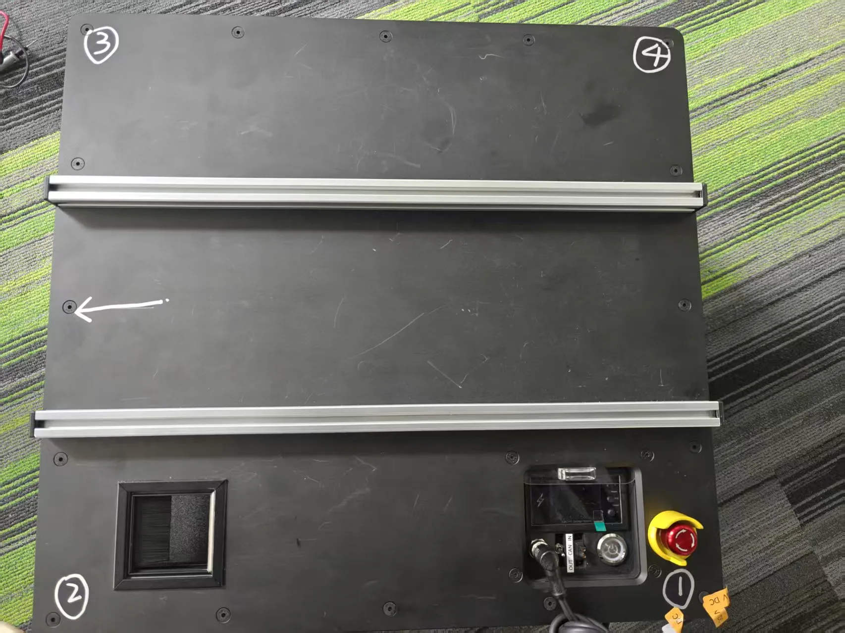
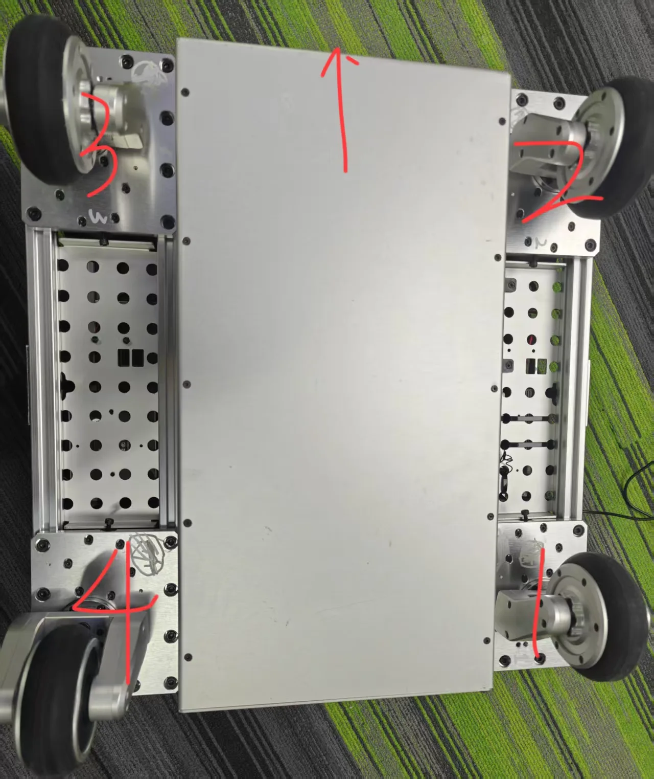
Determine the correct motor numbering using the head orientation and the numbering diagram above, then label each motor accordingly.
1.2 Configuration steps
1. Preparation
- Connect the CAN adapter and start the configuration environment
- Ensure the CAN bus termination resistor is correct (120 Ω)
- Connect only one motor at a time to the CAN bus
Alternative: host-PC upper computer
You can also configure parameters via the PC upper-computer tool. All motors must be set to speed mode with the parameters below:
4310:
POSITION_MAX=3.1415926,  POSITION_MIN=-3.1415926,
VELOCITY_MAX=30,         VELOCITY_MIN=-30,
TORQUE_MAX=10,           TORQUE_MIN=-10,

6215:
POSITION_MAX=12.5,       POSITION_MIN=-12.5,
VELOCITY_MAX=45,         VELOCITY_MIN=-45,
TORQUE_MAX=10,           TORQUE_MIN=-10,
2. Run the configuration tool
python dm_config_tools/config_dm_motor.py --channel can03. Steering motors (DM4310V — IDs 1, 3, 5, 7)
For each steering motor:
- a) Find the current ID: select
3) Find ID - b) Configure parameters and ID:
2) Configure MIT mode motor1) 4310V1) Change ID- Enter the old ID and the new ID from the table
- The tool sets automatically: MIT mode · max position 3.1415927 rad · timeout 4000 ms · Master ID = CAN ID + 16
4. Drive motors (DMH6215 / DM4310V — IDs 2, 4, 6, 8)
For each drive motor:
- a) Find the current ID: select
3) Find ID - b) Configure parameters and ID:
1) Configure speed mode motor- Select the model: DMH6215 →
2) 6215, DM4310V →1) 4310V 1) Change ID- Enter the old ID and the new ID from the table
- The tool sets automatically: speed mode · speed gains KP=0.006, KI=0.004 · timeout 4000 ms · Master ID = CAN ID + 16
5. Verify
- Repeat until all 8 motors are configured
- Validate parameters after each motor
- Confirm all IDs are correct with no conflicts
1.3 Verification script
After configuring all motor IDs and parameters, run the verification script:
# Drive motor defaults to 6215
python production_sop/flow_base/verify_motor_config.py

# If the drive motor is 4310V:
python production_sop/flow_base/verify_motor_config.py --drive-motor-type 4310
The script reads (does not move) each motor ID 1–8, confirms IDs are correct and conflict-free, checks parameters, and prints a diagnostic report. Safe to run in any state as long as all motors are connected and powered. Expected result: all 8 motors read back parameters with no communication errors.
2. Drive-Motor Direction
The "forward" rotation of every drive motor is defined as clockwise (CW) when viewed along the motor output shaft toward the caster wheel (i.e. looking from the motor shaft end toward the load). The base moves forward along the indicated direction when the motor turns as shown.
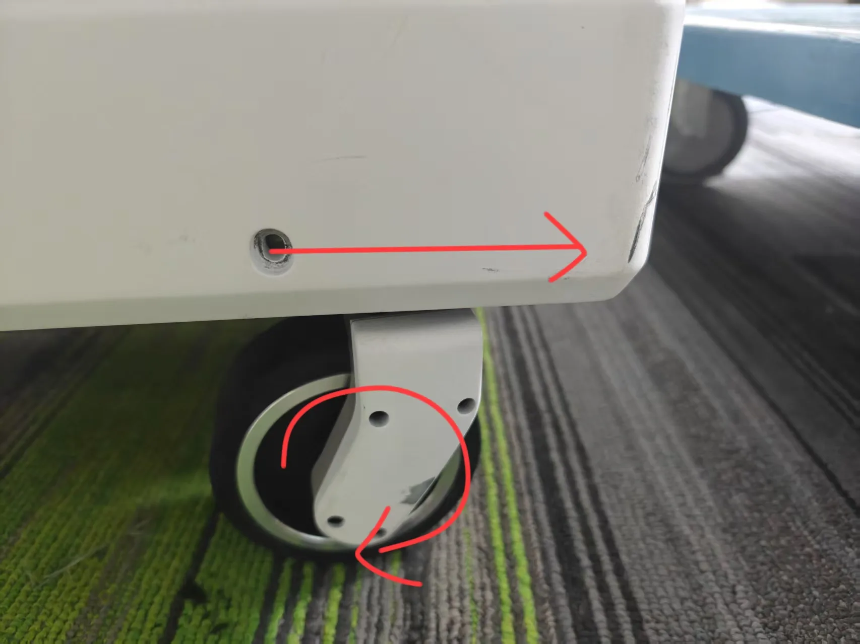
This is double-checked later by the test program — if a motor is reversed, reinstall the motor or wheel.
3. Steering Zero Calibration
Only the steering motors require zero calibration. Each steering zero must correspond to the wheel pointing straight ahead. Calibrate all steering motors together so the wheels are parallel and aligned.
Steps
- Physical alignment
- With the motors disabled, manually align each caster
- Ensure the wheels are parallel to the base's longitudinal axis and point straight ahead
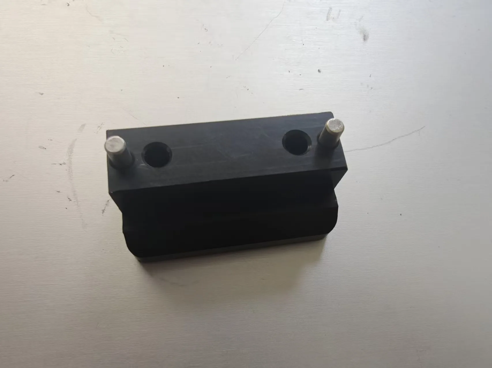
- Use the alignment pin for precision
- Set the zero positionbash
# zero one steering motor at a time python i2rt/motor_config_tool/set_zero.py --channel can0 --motor_id 1- Run once per steering motor ID (1, 3, 5, 7)
- The current position is saved as that motor's hardware zero
- Omitting
--motor_idzeros all motors 1–7 at once — pass an explicit ID to zero a single steering motor
4. System Parameters
4.1 Chassis geometry
Kinematics rely on the following geometry — the chassis design must follow it exactly:
| Parameter | Value | Meaning | Unit |
|---|---|---|---|
| h_x, h_y | h_x = [0.2, 0.2, -0.2, -0.2] h_y = [-0.2, 0.2, 0.2, -0.2] | Steering kingpin centers relative to the robot geometric center | m |
| b_x | -0.020 | Longitudinal offset from kingpin center to wheel center | m |
| b_y | 0.0 | Lateral offset from kingpin center to wheel center | m |
| r | 0.05 | Drive wheel radius | m |
4.2 Motion limits
| Parameter | Value | Notes |
|---|---|---|
| Max linear velocity | (0.5, 0.5) m/s | X–Y max |
| Max angular velocity | 1.57 rad/s | About Z |
| Max linear acceleration | (0.25, 0.25) m/s² | X–Y max |
| Max angular acceleration | 0.79 rad/s² | About Z |
5. Functional Verification
Bench test with wheels off the ground
Before running the automated tests, place the base upside-down so the motors and wheels are suspended and do not touch the ground. This prevents unintended motion, avoids wheel-to-ground friction skewing motor data, and makes it easy to observe the wheel mechanisms.
5.1 Running the tests
python production_sop/flow_base/test_base.py --mode 1    # Drive-motor direction
python production_sop/flow_base/test_base.py --mode 2    # Steering zero
python production_sop/flow_base/test_base.py --mode 3    # Lateral translation
python production_sop/flow_base/test_base.py --mode 4    # Diagonal motion
python production_sop/flow_base/test_base.py --mode 5    # Combined motion
5.2 Test details
Mode 1 — Drive-motor direction
- Command:
vehicle.set_target_velocity([1, 0, 0], frame="local") - Expected: all four wheels stay straight; the base drives in a straight line
- Check: straight-line trajectory, no yaw · Duration: forward 10 s, backward 10 s
| Symptom | Cause | Fix |
|---|---|---|
| Base reverses instead of going forward | Drive-motor direction misconfigured | Reconfigure drive-motor direction |
| Trajectory drifts left/right | 1. Steering zero inaccurate 2. Chassis geometry off | 1. Recalibrate steering zero 2. Re-measure chassis dimensions |
| Base moves forward while rotating | Left/right drive-motor directions inconsistent | Check and reconfigure drive-motor direction |
Mode 2 — Steering zero
- Command:
vehicle.set_target_velocity([0, 0, 1], frame="local") - Expected: wheels turn inward; the base rotates clockwise in place
- Check: no translation, stable rotation center · Duration: CW 10 s, CCW 10 s
| Symptom | Cause | Fix |
|---|---|---|
| Base translates instead of rotating in place | Steering zero inaccurate | Recalibrate steering zero |
| Rotates the wrong way (CCW) | Steering-motor direction misconfigured | Reconfigure steering-motor direction |
| Rotation unstable / jittery | Inconsistent steering zeros | Recalibrate all steering zeros |
Mode 3 — Lateral translation
- Command:
vehicle.set_target_velocity([0, 1, 0], frame="local") - Expected: wheels turn 90°; the base translates sideways
- Check: heading stays constant · Duration: right 10 s, left 10 s
| Symptom | Cause | Fix |
|---|---|---|
| Base moves the wrong lateral direction | Frame definition or drive-motor direction wrong | Reconfigure drive-motor direction |
| Heading rotates during translation | Steering zero inaccurate | Recalibrate steering zero |
| Wheel steer angle is not 90° | Steering zero offset | Recalibrate steering zero |
Mode 4 — Diagonal motion
- Command:
vehicle.set_target_velocity([1, 1, 0], frame="local") - Expected: the base moves along a 45° diagonal
- Check: direction accuracy · Duration: diagonal 10 s, reverse diagonal 10 s
| Symptom | Cause | Fix |
|---|---|---|
| Motion is not 45° | 1. X/Y drive speeds mismatched 2. Chassis geometry inaccurate | 1. Check drive-motor config 2. Re-measure chassis dimensions |
| Diagonal motion unstable | Steering/drive coordination issue | Recalibrate steering zero, check motor parameters |
Mode 5 — Combined motion
- Command:
vehicle.set_target_velocity([1, 0, 1], frame="local") - Expected: forward motion while rotating (spiral path)
- Check: translation and rotation execute together · Duration: 10 s
| Symptom | Cause | Fix |
|---|---|---|
| Only translation or only rotation | One motor class malfunctioning | Check drive and steering motor config separately |
| Irregular spiral | Multi-motor coordination issue | Re-check all motor config and zero calibration |
5.3 Joystick control test
python production_sop/flow_base/joystick_control.py- Before launching: set the start button and switch the Logitech receiver to D mode
- After launching: let it sit for a few seconds, then nudge the sticks gently (residual state at startup can make the base "twitch") — wait until the read values settle toward 0
- Left stick: X–Y translation · Right stick X: spin · Controller: Xbox/PS4-compatible
6. Base Controller Run Test
Once configuration and tests pass, run the base controller for final verification.
python -m i2rt.flow_base.flow_base_controllerExpected: the controller initializes all motors, responds to joystick input, and drives the base smoothly with no abnormal vibration or noise; each axis responds accurately.
| Symptom | Cause | Fix |
|---|---|---|
| Controller fails to start | 1. CAN comms error 2. Motor ID misconfigured | 1. Check CAN connection 2. Run the verification script |
| Joystick unresponsive | Controller not connected / init failed | Check connection, re-plug USB |
| Base motion not smooth | 1. Steering zero inaccurate 2. Motor parameters wrong | 1. Recalibrate zeros 2. Check motor parameters |
| Wrong motion direction | Motor direction misconfigured | Reconfigure motor direction |
Safety
- Run first tests in an open area
- Keep the E-stop within reach at all times
- Watch motor temperature and CAN status while running
- Stop immediately and re-check configuration if anything looks wrong
See Also
- Linear Bot — Flow Base + linear rail lift + YAM arm
- Flow Base hardware setup
- Flow Base demo